Some ideas are as easy to say yes to as they are difficult to actually pull off.
Deciding to renovate a kitchen by yourself is one. Setting up a robotic cell and do live conformal 3D printing at a trade show is another. Nonetheless, three months ago we joined a team of exceptional people and took on the challenge.
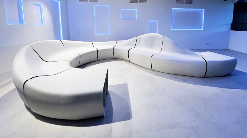
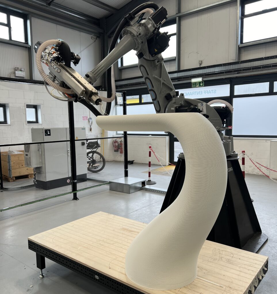
The result was an impressive display of how industrial robots can be used to create complex large scale structures. Multi-axis 3D printing and machining were combined to manufacture a series of double curved geometries which, assembled, formed the nose cone of a wind energy tower.
With ADAXIS AdaOne, we had the exciting task of making the robot come to life through multi-axis path planning and process optimization.
At the end of last year, the team at Research Institutes of Sweden (RISE) floated the idea to setup a demo of live robotic printing at the Maintenance Fair and Additive Intelligence conference in Gothenburg, Sweden. It was an enticing proposal – a robot and (almost) full creative freedom. We joined a group of talented people and companies to make it happen: ADDICT3D, ABB, KFM Maskin, SICK, Micro-Epsilon, RSP, and Troax, with support from Svenska Mässan and Produktion2030.
Bringing a printer to a trade show requires two things: hardware and vast amounts of optimism. In this case the robot cell had to be assembled from scratch and then installed on site. A challenge in itself, but expertly handled by RISE, ADDICT3D and ABB. The robot cell was based on an ABB IRB6700 220/3.0 industrial robot with a 35 mm diameter pellet extruder from KFM Maskin. A tool changer made it possible to switch from the extruder to a milling spindle. Robot safety was handled by floor mounted laser scanners from SICK. Finally, a laser profile scanner and a thermal camera from Micro-Epsilon made it possible to check the part geometry and temperature across each layer while printing.
Before moving on to the actual printing, let’s take a moment to talk about extruder control. Fascinating subject. In this integration, the extruder motor is controlled as an external axis. The benefit is that the screw rotation is synchronized with the real motion of the robot. This is a common way to adapt the extrusion to the real robot speed and avoid excessive material at sharp corners where the robot needs to decelerate and accelerate to change direction. It can be particularly important during non-planar printing when the robot speed many times is limited by how fast the robot can reorient the tool.
Ok, now let’s get back to the printing.
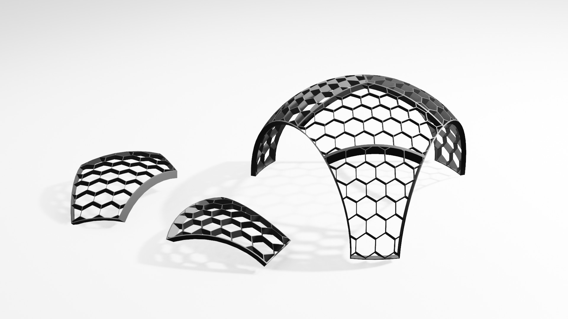
The geometry of choice was masterminded by Woodrow Wiest at RISE: the outer shape of a nose cone for a wind energy tower, split into six individual pieces – three each of two unique geometries. Printing it turned out to be what we in Sweden would call a “trestegsraket” (three stage rocket):
- Printing of formwork which can be used as substrate for the printing.
- Machining of the formwork to final geometry, including adding reference points for part alignment after moving it to the trade show.
- Non-planar printing of the parts on top of the machined substrate.
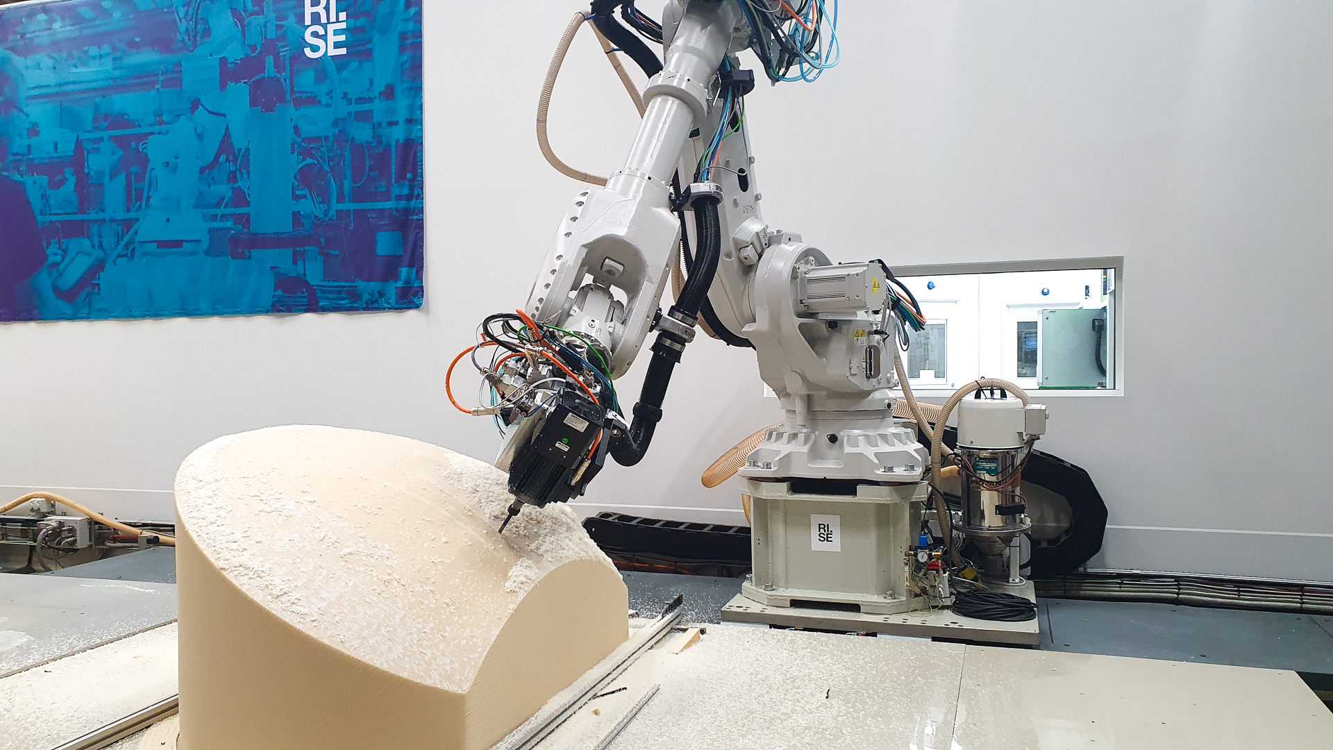
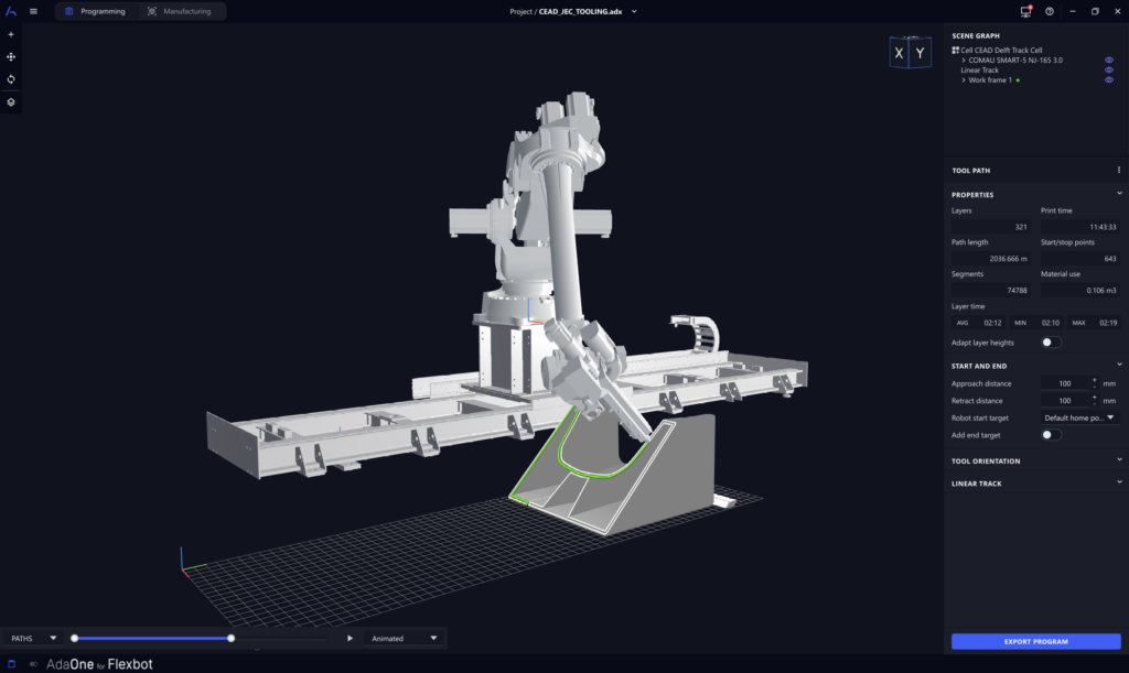
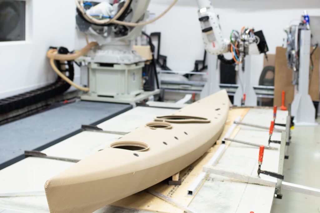
The formwork was printed in UPM Formi, a PLA based biocomposite material. The shape was specifically designed to be printed using 45 degree angle printing. This allowed us to manage the difficult overhang of the top surface without the need for internal supports. After printing, the extruder was switched to a milling spindle and the formwork machined to its final geometry using an end mill cutter. Holes for a fork lift were cut in the side to make it easier to handle. The final step was to add a series of drilled holes in the top surface to be used for alignment at the trade show.
Printing on a cold substrate can be challenging. We wanted the final part to stick to the surface but not stick too much. In the end, we found a balance between the substrate surface roughness, a thinner first layer, and a reduced print speed for the first layer.
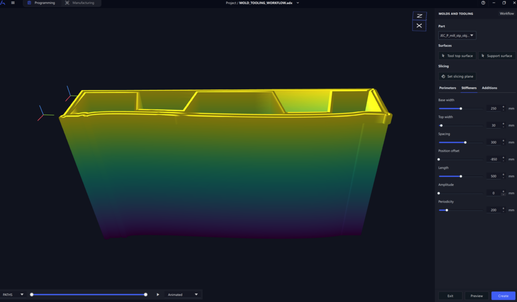
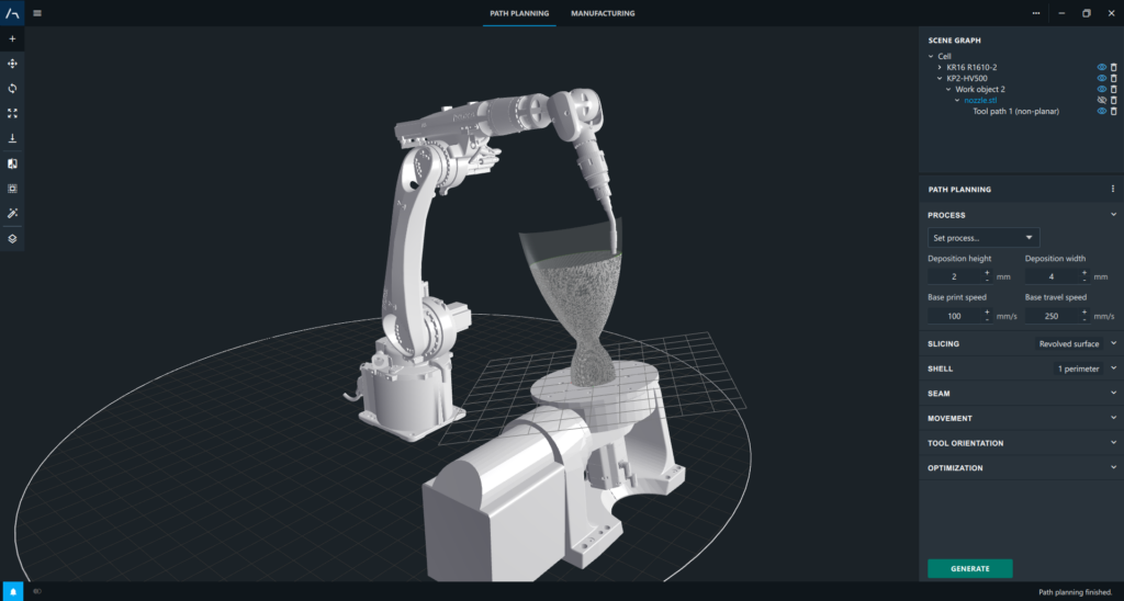
AdaOne offers a variety of path planning strategies for different purposes, for example planar angled, multi-planar, radial, conical, and non-planar. In this case, we chose to use an algorithm dedicated to generating tool paths for cladding of material on top of an existing surface. It is most commonly used for surface functionalization or part repair when using Wire Arc AM (WAAM) or Wire Laser AM (WLAM).
Using the cladding approach is fairly straightforward. You simply import the part as a STEP file, select which surface you would like to use, and define how many layers of material to add. After a few seconds you will have conformal tool paths with tool orientation normal to the selected surface. In this case, we generated two perimeters and a low density hexagonal infill.
Initial tests showed that the material deposition, first layer adhesion, and robot interpolation all worked very well. However, we quickly realized the need to optimize the robot movement based on two key criteria:
- Reachability. At the trade show, the idea was to use two different substrates so that we could print two parts one after the other. Both substrates had to be placed within the robot reach and the target orientation optimized so that the robot could access the entire tool path.
- Material feed. During non-planar printing, it is inevitable to hit tool orientations where material does not properly feed into the hopper. This is fine as long as the extruder is changing orientation often. Unfortunately, in our case the layer time was approximately 4 minutes and the extruder would spend significant time in a non-optimal orientation.
We needed to find an optimal way to dynamically rotate the extruder around its C axis (tool axis) and ensure both reachability and material feed. Easier said than done but exactly the kind of challenge we love at ADAXIS.
The solution was two-fold:
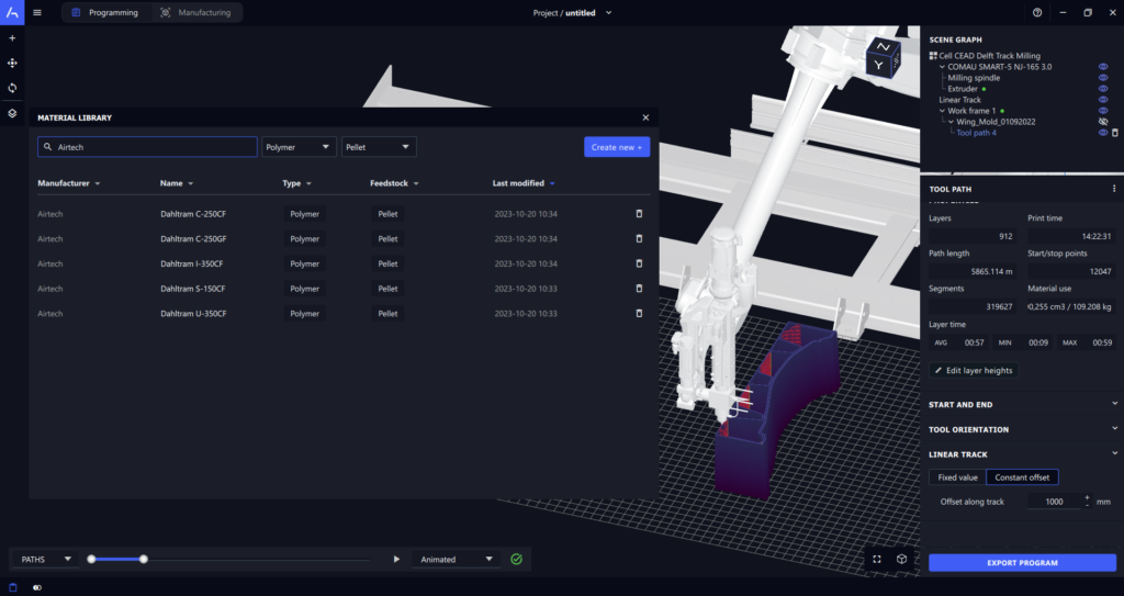
- Real-time reachability check. A new feature in AdaOne, visible above, which checks for reachability issues and singularities for the entire tool path, in real-time, directly after making any change to the robot movement. This allowed us to quickly iterate through possible part positions and tool orientations.
- C-axis interpolation. A way to dynamically twist the extruder around its own axis, thereby maximizing both reach and minimizing risk of material starvation.
To control the tool orientation in this way we had to use another of our recent developments. At RISE, they use the 3D Printing PowerPac from ABB to execute programs on the robot controller. One of the many benefits is the possibility to run large programs with millions of robot targets without any interruption. However, a limitation of the PowerPac has been that it is not possible to define the tool axis/C-axis in the type of g-code it supports. Luckily, through our close collaboration with ABB, we have been able to create a new dedicated file format (.ada3dp) which is currently being beta tested. This file format offers increased control of the tool path and a tighter integration between AdaOne and the 3DP PowerPac.
With hardware and optimal tool path sorted it was time to print.
The printing was an immediate hit at the Maintenance Fair. Robotic 3D printing is now so common at Formnext that it is easy to forget that there is a world outside of the additive manufacturing bubble where it is still a new technology.
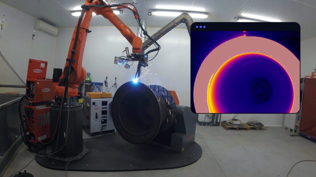
During the trade show, we had the chance to explore another topic where we are currently putting a lot of effort: real-time monitoring and control. Courtesy of friends at Micro-Epsilon, we were able to monitor the printing using a scanCONTROL high performance laser scanner mounted on the extruder and a thermal imaging camera.
Each combination of a material and extruder will have an optimal layer time range where both the inter-layer bonding and the cooling are acceptable. Typical values for our setup would be 45 – 90 seconds per layer. In this case, we were spending close to 4 minutes on each layer. One of the reasons for that was that we wanted the print to take around 1.5 hours to finish. In the video below you can see that the temperature of the previous layer is hovering just above 52°C. Realistically, this would need to be optimized.
There are a number of important takeaways from this work.
First of all, I find it incredible that it was possible to put together a state-of-the-art robotic printer for a live demo from basically nothing in just a few months. It shows the amount of work and dedication put into this technology from people like Woodrow Wiest, Samuel Johansson, Lenny Tönnäng, Jan Johansson, Johan Åkerman, Thomas Bruce and the entire AM team at RISE, Anders Spaak at ABB, Jonathan Olofsson at KFM Maskin, Christian Magnusson and Jonas Zitek at ADDICT3D, and many others.
Second, this project highlighted the versatility of robotic printing and how combining multiple manufacturing technologies can be a game-changer in creating a new category of large scale 3D printed parts. Instead of only thinking about design for large scale additive we also need to dive into design for robotic additive and hybrid manufacturing.
Finally, it was also a lot of fun. And that should not be an underestimated driver of innovation.
Emil Johansson is the Chief Product Officer of ADAXIS. He has been working with robotic additive manufacturing for the last 8 years and is in a constant pursuit to make industrial robotics more easy to use.